


Configuring Frame Relay
Configuring the MAX as a Frame Relay switch
MAX 6000/3000 Network Configuration Guide Preliminary January 4, 2001 5-25
Configuring the MAX as a Frame Relay switch
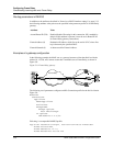
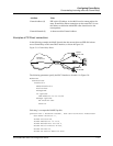
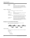
As a Frame Relay switch, the MAX receives frames on one DLCI interface and transmits them
on another one. The decision to forward frames is made on the basis of circuit name
assignments.
To use the MAX as a switch, you must configure a circuit that pairs two DLCI interfaces.
Instead of going to the layer 3 router for a decision on which interface to forward the frames, it
relies on the circuit name to relay the frames to the paired interface. A circuit is defined in two
Connection profiles, one for each endpoint of the circuit.
Note: When it is operating as a switch, the MAX relays all frames received on one endpoint
of the circuit to the other endpoint of the circuit. It does not examine the packets at OSI layer 3.
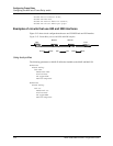
Overview of circuit-switching options
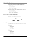
With a Frame Relay circuit configuration, the MAX can operate as a switch on UNI-DCE
interfaces, NNI interfaces, or a combination of the two. NNI is not required.
Routing parameters or attributes should be disabled for switched connections.
Note: Make sure that the Enabled parameter is set to Yes in the Answer-Defaults FR-Answer
subprofile.
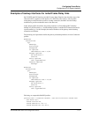
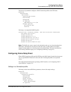
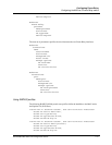
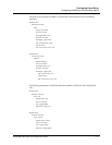
Settings in a Connection profile
Following are the relevant circuit parameters, shown with sample settings:
Ethernet
Connections
caller-1
Station=caller-1
Active=Yes
Encaps=FR-Cir
Encaps options
FR Prof=max
DLCI=100
FR Circuit=frcir1
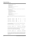
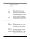
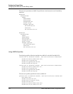
Parameter Specifies
Encaps Encapsulation protocol. Both endpoints of the circuit must specify
Frame-Relay-Circuit encapsulation.
FR Prof Name of the Frame Relay profile that defines the datalink.
DLCI A DLCI for this PVC endpoint.The DLCI must be obtained from
a Frame Relay provider. The MAX does not allow you to enter
duplicate DLCIs, except when they are carried by separate
physical links specified in different Frame Relay profiles.