


5-10 Preliminary January 4, 2001 MAX 6000/3000 Network Configuration Guide
Configuring Frame Relay
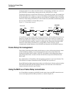
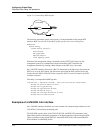
Defining Frame Relay link operations
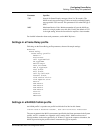
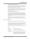
Figure 5-4. Frame Relay DTE interface
The following parameters specify nailed group 11 as the bandwidth for the sample DTE
interface. Make sure that the Frame-Relay profile specifies the correct nailed group.
Ethernet
Frame Relay
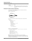
Frame Relay profile
Active=Yes
FR Type=DTE
Nailed Grp=11
Link Mgmt=Q.933A
With these link management settings, the MAX uses the CCITT Q.933 Annex A link
management protocol to communicate with the Frame Relay DCE. It initiates link
management functions by sending a Status Enquiry to the DCE every 10 seconds.
On a UNI-DTE interface, the state of a DLCI is determined by the Full status report from the
DCE or by an async PVC update. The Full status report from the DCE specifies active and
inactive and new DLCIs. If the DCE does not specify a DLCI as active or inactive, the DTE
considers it inactive.
Following is a comparable RADIUS profile:
frdlink-max-1 Password="ascend", User-Service=Dialout-Framed-User
Ascend-FR-Profile-Name="fr-dte",
Ascend-Call-Type=Nailed,
Ascend-FR-Type=Ascend-FR-DTE,
Ascend-FR-Nailed-Grp=11,
Ascend-FR-Link-Mgt=Ascend-FR-Q-933A,
Ascend-Data-Svc=Nailed-64K
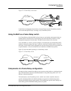
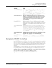
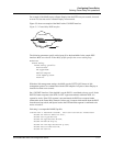
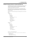
Examples of a UNI-DCE link interface
On a UNI-DCE interface, the MAX acts as the network side communicating with the user side
(UN-DTE) of a Frame Relay terminating unit.
The UNI-DCE uses the values of the T392, DCE N392, and DCE N393 parameters in the
Frame Relay profile to define the parameters of the Status Enquiries expected from the DTE.
(These correspond to the Ascend-FR-T392, Ascend-FR-DCE-N392, and Ascend-FR-DCE-
N393 attributes in a RADIUS profile.)
FR switch
Frame Relay
DCE DTE