DEFINITY ECS Release 8.2 ATM Installation,
Upgrades, and Administration
555-233-124
Issue 1
April 2000
Installing a DEFINITY ECS ATM-PNC
3-2Equipment Installation
3
Slot restrictions for an ATM interface circuit packs are similar to expansion
interface circuit packs:
■ PPN: ATM interface circuit packs used for ATM-PNC must occupy the slots
labeled EXPANSION INTERFACE.
■ EPNs: ATM interface circuit packs used for ATM-PNC can occupy slot 1
(and 2 if duplicated) on carrier A, and slot 2 (and 3 if duplicated) on carrier
B
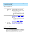
Follow the steps in Table 3-1
to ensure that
■ the applicable equipment is installed correctly.
■ the customer’s configuration is properly recorded (use worksheet in
Appendix A, ‘‘Baselining the Customer’s Configuration’’
).
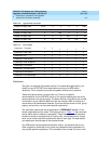
Table 3-1. General installation process
√ Step Action Description
1. Install DEFINITY ECS
switch
Refer to the appropriate installation book
See ‘‘DEFINITY ECS configurations’’ on page 1-6
for
connection schematics.
2. Install ATM switch(es)
or access
concentrators
Refer to your ATM switch’s quick reference guide.
3. Check the distances
from the ATM switch
to the DS1 timing
source
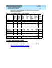
Use the information in Table 3-3
to determine the
maximum cable run lengths for the configuration for more
information.
4. Install ATM interface
circuit pack
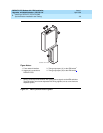
Insert the TN2305/TN2306 circuit pack(s) into the
appropriate slot(s).
5. Route the fiber optic
cables between the
ATM switch and the
DEFINITY PPN and
EPNs.
Follow the fiber pass-through procedure in the appropriate
installation book.
!
WARNING:
Be sure that the fiber optic cable is secured so that
the door of the DEFINITY ECS switch does not pinch
or bend the cable.
6. Connect the fiber
optic cables
Connect the fiber optic cables to the ATM switch.
NOTE:
If the installation uses the customer’s existing fiber,
you may need an ST-to-SC adapter (1 included in
Fiber Pass-Through Kit).
Continued on next page


