DEFINITY ECS Release 8.2 ATM Installation,
Upgrades, and Administration
555-233-124
Issue 1
April 2000
Installing a DEFINITY ECS ATM-PNC
3-11Synchronization Installation and Testing
3
Synchronization splitter connections
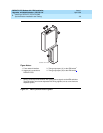
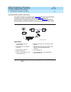
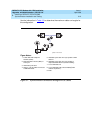
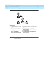
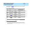
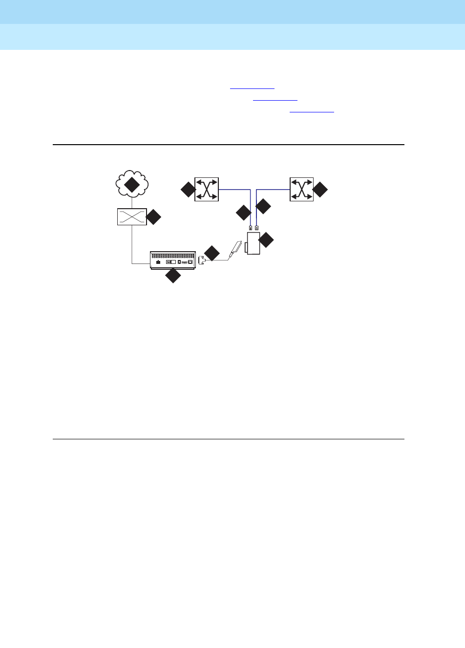
The splitter connects to a timing source. Figure 3-6 shows the synchronization
connections through a DSU/CSU (400A), and Figure 3-7
shows the
synchronization connections through an ICSU (400A). Figure 3-8
shows the
synchronization connections directly to the timing source (401A, 402A, 403A).
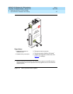
Figure 3-6. Synchronization connections through an external DSU/CSU
(400A
)
Figure Notes:
1. Public Switched Telephone
Network (PSTN)
2. Main distribution frame (MDF) or
smart jack.
3. Channel service unit (CSU)
4. H600-307-GR2 cable
5. 400A T1 (100 Ω) splitter connects
to the DEFINITY ECS
6. H600-383 quad cable from sync splitter to ATM
switch A
7. H600-383 quad cable from sync splitter to ATM
switch B (critical reliability/ATM network
duplication)
8. Lucent ATM switch A
9. Lucent ATM switch B (critical reliability/ATM
network duplication)
cydaatm2 LJK 020100
1
3
4
5
6
7
2
8 9


