


CHAPTER 8 USB FUNCTION
User’s Manual U12978EJ3V0UD
104
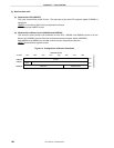
(5) Transmit data banks 0 and 1
(a) Transmit data PID banks 0 and 1 (USBTD0 and USBTD1)
USBTD0 and USBTD1 correspond to the transmit buffer 0 ID area and transmit buffer 1 ID area,
respectively. USBTD0 and USBTD1 store DATA0 (C3H) or DATA1 (4BH).
USBTD0 and USBTD1 are set with an 8-bit memory manipulation instruction.
RESET input makes both USBTD0 and USBTD1 undefined.
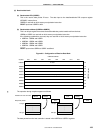
(b) Transmit data bank 0 address (USBT00 to USBT07) and transmit data bank 1 address (USBT10 to
USBT17)
These are 8-byte registers that store the data to be transferred to the host. USBT00 to USBT07 and
USBT10 to USBT17 correspond to transmit buffer 0 of the data area and transmit buffer 1 of the data area,
respectively. Because CRC redundant bits (16 bits) are always appended to packets sent from these
registers, these registers cannot be used for transmitting handshake packets.
USBT00 to USBT07 and USBT10 to USBT17 are set with an 8-bit memory manipulation instruction.
RESET input makes this area undefined.
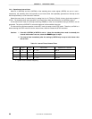
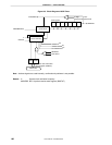
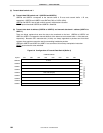
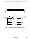
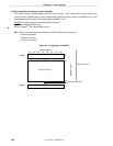
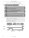
Figure 8-6. Configuration of Transmit Data Bank 0 (Buffer 0)
20H
07H 06H 05H 04H 03H 02H 01H 00H
21H
22H
23H
24H
25H
26H
27H
28H
USBTD0
USBT00
USBT01
USBT02
USBT03
USBT04
USBT05
USBT06
USBT07
USBPOW address
USBPOB address
Symbol
ID area
Data area (8 bytes)