


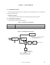

CHAPTER 5 CLOCK GENERATOR
User’s Manual U12978EJ3V0UD
77
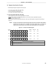
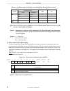
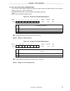
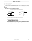
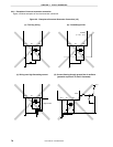
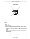
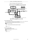
Figure 5-4. Examples of Incorrect Resonator Connection (2/2)
(e) Signals are fetched
V
SS0
X1 X2
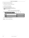
5.4.3 Frequency divider
The frequency divider divides the output of the system clock oscillator (fX
) to generate various clocks.
5.5 Clock Generator Operation
The clock generator generates the following clocks and controls the operation modes of the CPU, such as the
standby mode.
• System clock f
X
• CPU clock fCPU
• Clock to peripheral hardware
The operation of the clock generator is determined by the processor clock control register (PCC), as follows.
(a) The slow mode (1.33
µ
s: at 6.0 MHz operation) of the system clock is selected when the RESET signal is
generated (PCC = 02H). While a low level is being input to the RESET pin, oscillation of the system clock
is stopped.
(b) Two types of minimum instruction execution time (0.33
µ
s and 1.33
µ
s: at 6.0 MHz operation) can be
selected by the PCC setting.
(c) Two standby modes, STOP and HALT, can be used.
(d) The clock pulse for the peripheral hardware is generated by dividing the frequency of the system clock. So,
the other hardware stops when the system clock stops (except for external clock pulses).