


CHAPTER 6 8-BIT TIMER/EVENT COUNTERS 00 AND 01
User’s Manual U12978EJ3V0UD
87
6.4.2 Operation as external event counter (timer 01 only)
The external event counter counts the number of external clock pulses input to the TI01/P26/INTP0/TO01 pin by
using timer counter 01 (TM01).
To operate the 8-bit timer/event counter as an external event counter, the following settings are required.
<1> Disable operation of 8-bit timer counter 01 (TM01) by setting TCE01 (bit 7 of 8-bit timer mode control
register 01 (TMC01)) to 0.
<2> Specify the rising/falling edge of TI01 (see Table 6-6), and set TO01 to output-disabled (TOE01 (bit 0 of
TMC01) = 0).
<3> Set count values to CR01.
<4> Enable operation of TM01 by setting TCE01 to 1.
Each time the valid edge specified by bit 1 or 2 (TCL011 or TCL010) of TMC01 is input, the value of 8-bit timer
counter 01 (TM01) is incremented.
When the count value of TM01 matches the value set to CR01, the value of TM01 is cleared to 0 and TM01
continues counting. At the same time, an interrupt request signal (INTTM01) is generated.
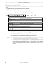
Figure 6-8 shows the timing of external event counter operation (with rising edge specified).
Caution When the TMC01 count clock is set and the operation of TM01 is enabled simultaneously by an
8-bit memory manipulation instruction, an error of more than 1 clock may occur in 1 cycle after
the timer has been started. Therefore, be sure to follow the settings above when the 8-bit
timer/event counter is operating as an external event counter.
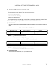
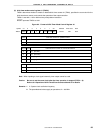
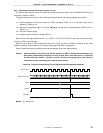
Figure 6-8. Timing of External Event Counter Operation (with Rising Edge Specified)
TI01 pin input
TM01 count value
CR01
TCE01
INTTM01
00 01 02 03 04 05
N – 1
N00010203
N
Remark N = 00H to FFH