


CHAPTER 4 PORT FUNCTIONS
User’s Manual U12978EJ3V0UD
68
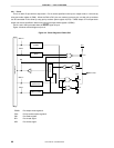
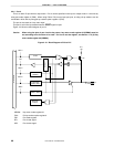
4.2.4 Port 4
This is an 8-bit I/O port with an output latch. Port 4 can be specified in the input or output mode in 1-bit units by
using port mode register 4 (PM4). When using P40 to P47 pins as input port pins, on-chip pull-up resistors can be
connected in 8-bit units by using pull-up resistor option register 0 (PU0).
The port is also used as a key return input.
This port is set in the input mode when the RESET signal is input.
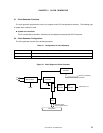
Figure 4-10 shows a block diagram of port 4.
Caution When using the pins of port 4 as the key return, key return mode register 00 (KRM00) must be
set according to the function to be used. For how to set the register, see Section 11.3 (5) Key
return mode register 00 (KRM00).
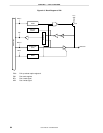
Figure 4-10. Block Diagram of P40 to P47
WRKRM
Internal bus
VDD0
P40/KR00 to
P47/KR07
WR
PU0
RD
WR
PORT
WRPM
PU04
Alternate
function
Output latch
(P40 to P47)
PM40 to PM47
KRM000 to
KRM007
Selector
P-ch
KRM00: Key return mode register 00
PU0: Pull-up resistor option register 0
PM: Port mode register
RD: Port 4 read signal
WR: Port 4 write signal