


CHAPTER 8 USB FUNCTION
User’s Manual U12978EJ3V0UD
110
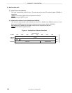
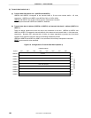
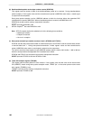
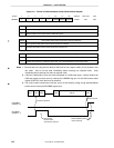
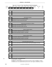
Figure 8-11. Format of Data/Handshake Packet Receive Mode Register
Symbol 67 5 4 3 <2> <1> <0>
00000
RESMOD
DINTEN
DWRMSK
RESMOD
USB reset signal detection mode setting
0
1
FF66H
Address
URXMOD
After reset
00H
R/W
R/W
Reject USB reset signal less than 3.0 s SE0 (Single-ended 0) period.
Detect transition from J state to SE0 as USB reset signal.
DINTEN Data packet receive status synchronous interrupt enable flag
0
1
Do not generate data packet receive status synchronous interrupt.
Generate data packet receive status synchronous interrupt
Note 3
.
DWRMSK
Data/handshake packet write disable setting
0
1
Enable write operation to all addresses in data/handshake packet receive buffer.
Disable write operation to addresses greater than 11H in data/handshake packet receive buffer.
Note 1
Note 2
µ
Notes 1. Because this is the flag used to detect a USB reset in bus suspend mode, do not set data in bus
idle mode. And do not set data immediately before entering bus suspend mode. Clear
immediately when returning from the bus suspend mode.
2. If the bus is disturbed by noise, the noise is detected as a USB reset signal. Confirm whether the
USB reset signal has been input by checking the URESRX flag (bit 4 of the USB receive status
register (RXSTAT)) more than once by software.
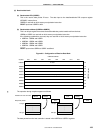
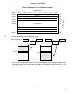
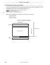
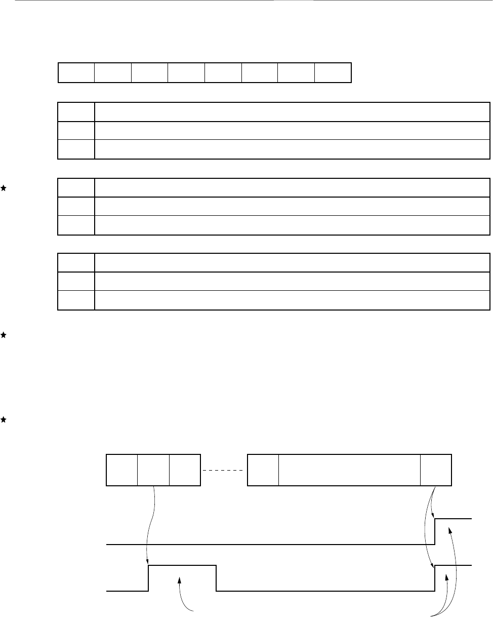
3. The receive status synchronous interrupt occurs at the following timing during data/handshake
packet receive interrupt (INTUSBRD) signal input.
Packet ID detected
EOP received
Sync Data0 Data1 DataX CRC16 EOP
INTUSBRD
(DINTEN = 0)
INTUSBRD
(DINTEN = 1)
Data packet
receive status
synchronous interrupt
Data/handshake packet
receive interrupt