


CHAPTER 4 PORT FUNCTIONS
User’s Manual U12978EJ3V0UD
61
4.2.2 Port 1
This is an 8-bit I/O port with an output latch. Port 1 can be specified in the input or output mode in 1-bit units by
using port mode register 1 (PM1). When the P10 to P17 pins are used as input port pins, on-chip pull-up resistors
can be connected in 8-bit units by using pull-up resistor option register 0 (PU0). CMOS output or N-ch open-drain
output can also be specified in 8-bit unit by using port output mode register 0 (POM0).
Port 0 is set in the input mode when the RESET signal is input.
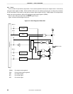
Figure 4-3 shows a block diagram of port 1.
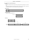
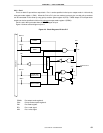
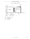
Figure 4-3. Block Diagram of P10 to P17
POM0: Port output mode register 0
PU0: Pull-up resistor option register 0
PM: Port mode register
RD: Port 1 read signal
WR: Port 1 write signal
RD
VDD0
P10 to P17
WR
POM0
WRPU0
WRPORT
WRPM
Output latch
(P10 to P17)
PM10 to PM17
PU01
P-ch
P-ch
N-ch
VDD0
POM01
Internal bus
Selector