


User’s Manual U12978EJ3V0UD
186
CHAPTER 13 RESET FUNCTION
The following two operations are available to generate reset signals.
(1) External reset input via RESET pin
(2) Internal reset by inadvertent program loop time detected by watchdog timer
External and internal reset have no functional differences. In both cases, program execution starts at the address
at 0000H and 0001H by RESET input.
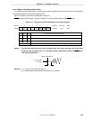
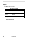
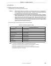
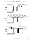
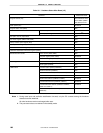
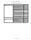
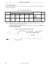
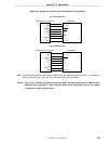
When a low level is input to the RESET pin or the watchdog timer overflows, a reset is applied and each of the
hardware is set to the status shown in Table 13-1. Each pin is high impedance during reset input or during the
oscillation stabilization time just after reset release.
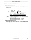
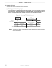
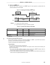
When a high level is input to the RESET pin, the reset is released and program execution is started after the
oscillation stabilization time (2
15
/fx) has elapsed. The reset applied by watchdog timer overflow is automatically
released after reset, and program execution is started after the oscillation stabilization time (2
15
/fx) has elapsed (see
Figures 13-2 through 13-4.)
Cautions 1. For an external reset, input a low level for 10
µ
µµ
µ
s or more to the RESET pin.
2. When the STOP mode is released by reset, the STOP mode contents are held during reset
input. However, the port pins become high impedance.
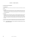
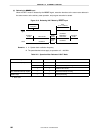
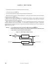
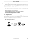
Figure 13-1. Block Diagram of Reset Function
RESET
Interrupt function
Count clock
Reset controller
Watchdog timer
Over-
flow
Reset signal
Stop