


CHAPTER 14
µ
µµ
µ
PD78F9801
User’s Manual U12978EJ3V0UD
192
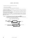
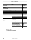
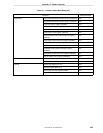
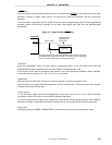
14.1.2 Communication mode
Use the communication mode shown in Table 14-2 to perform communication between the dedicated flash
programmer and
µ
PD78F9801.
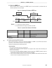
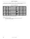
Table 14-2. Communication Mode List
TYPE Setting
Note 1
Communication
Mode
COMM PORT SIO Clock CPU Clock Flash Clock Multiple Rate
Pins Used Number of
V
PP
Pulses
3-wire serial
I/O
SIO ch-0
(3-wire, sync.)
100 Hz to
1.25 MHz
Note 2
Optional 1 to 5 MHz
Note 2
1.0 SI10/P22
SO10/P21
SCK10/P20
0
Pseudo-3-wire Port A
(pseudo-
3-wire)
100 Hz to
1 kHz
Optional 1 to 5 MHz
Note 2
1.0 P10 (serial clock input)
P11 (serial data output)
P12 (serial data input)
12
Notes 1. Selection items for TYPE settings on the dedicated flash programmer (Flashpro III (part no. FL-PR3,
PG-FP3)/Flashpro IV (part no. FL-PR4, PG-FP4)).
2. The possible setting range differs depending on the voltage. For details, refer to CHAPTER 16
ELECTRICAL SPECIFICATIONS.
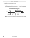
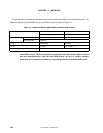
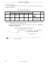
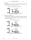
Figure 14-2. Communication Mode Selection Format
10 V
V
SS
V
DD
V
PP
V
DD
V
SS
RESET
12 n
V
PP
pulses