


User’s Manual U12978EJ3V0UD
220
CHAPTER 18 RECOMMENDED SOLDERING CONDITIONS
The
µ
PD789800 Subseries should be soldered and mounted under the following recommended conditions.
For details of the recommended soldering conditions, refer to the document Semiconductor Device Mounting
Technology Manual (C10535E).
For soldering methods and conditions other than those recommended below, contact an NEC Electronics sales
representative.
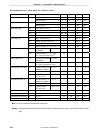
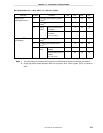
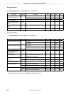
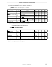
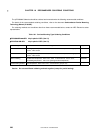
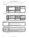
Table 18-1. Surface Mounting Type Soldering Conditions
µ
µµ
µ
PD789800GB-×××
××××××
×××-8ES: 44-pin plastic LQFP (10 ×
××
× 10)
µ
µµ
µ
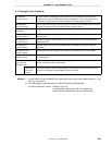
PD78F9801GB-8ES: 44-pin plastic LQFP (10 ×
××
× 10)
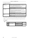
Soldering Method Soldering Conditions Symbol
Infrared reflow Package peak temperature: 235°C, Time: 30 seconds max. (at 210°C or higher),
Count: Twice or less
IR35-00-2
VPS Package peak temperature: 215°C, Time: 40 seconds max. (at 200 °C or higher),
Count: Twice or less
VP15-00-2
Wave soldering Solder bath temperature: 260°C max., Time: 10 seconds max., Count: Once,
Preheating temperature: 120°C max. (package surface temperature)
WS60-00-1
Partial heating method Pin temperature: 300°C max. Time: 3 seconds max. (per pin row) −
Caution Do not use different soldering methods together (except for partial heating).