


CHAPTER 6 8-BIT TIMER/EVENT COUNTERS 00 AND 01
User’s Manual U12978EJ3V0UD
83
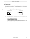
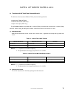
(2) 8-bit timer mode control register 01 (TMC01)
TMC01 determines whether to enable or disable 8-bit timer counter 01 (TM01), specifies the count clock for the
8-bit timer/event counter, and controls the operation of the output controller.
TMC01 is set with a 1-bit or 8-bit memory manipulation instruction.
RESET input sets TMC01 to 00H.
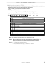
Figure 6-4. Format of 8-Bit Timer Mode Control Register 01
TCE010000
TCL011TCL010
TOE01TMC01
Symbol Address After reset R/W
FF57H 00H R/W
6<7> 54321<0>
TCL011
0
0
1
1
8-bit timer/event counter 01 count clock selection
TCL010
0
1
0
1
f
X
/2
4
f
X
/2
8
Rising edge of TI01
Note
Falling edge of TI01
Note
TCE01
0
1
8-bit timer counter 01 operation control
Operation disabled (TM01 is cleared to 0.)
Operation enabled
(375 kHz)
(23.4 kHz)
TOE01
0
1
8-bit timer/event counter 01 output control
Output disabled (port mode)
Output enabled
Note When inputting a clock signal externally, timer output cannot be used.
Caution Be sure to set the count clock after the timer operation is stopped (TCE01 = 0).
Refer to 6.4 Operation of 8-Bit Timer/Event Counters 00 and 01 for details.
Remarks 1. f
X
: System clock oscillation frequency
2. The parenthesized values apply to operation at f
X
= 6.0 MHz.