


CHAPTER 11 INTERRUPT FUNCTIONS
User’s Manual U12978EJ3V0UD
167
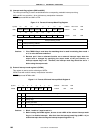
(1) Interrupt request flag registers (IF0 and IF1)
The interrupt request flag is set to 1 when the corresponding interrupt request is generated or an instruction is
executed. It is cleared to 0 when an instruction is executed upon acknowledgement of an interrupt request or
upon RESET input.
IF0 and IF1 are set with a 1-bit or 8-bit memory manipulation instruction.
RESET input sets IF0 and IF1 to 00H.
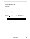
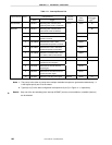
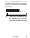
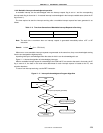
Figure 11-2. Format of Interrupt Request Flag Register
0
1
IF1 FFE1H 00H R/W
Interrupt request flag
No interrupt request signal is generated
Interrupt request signal is generated; interrupt request state
XXIFX
TMIF01 TMIF00 CSIIF10 KRIF00 0 0 PIF0 TMIF4IF0
R/W
FFE0H 00H R/W
0
USBTMIFUSBRTIFUSBRDIFUSBSTIF USBREIF
00
Symbol
Address After reset
<6> <5> <4> 3 2 <1><7> <0>
<6> <5> <4> <3> <2> 170
Cautions 1. The TMIF4 flag is R/W enabled only when the watchdog timer is used as an interval
timer. If watchdog timer mode 1 or 2 is used, set the TMIF4 flag to 0.
2. Because port 2 has an alternate function as an external interrupt input, when the
output level is changed by specifying the output mode of the port function, an
interrupt request flag is set. Therefore, the interrupt mask flag should be set to 1
before using the output mode.
3. If an interrupt is acknowledged, an interrupt request flag is automatically cleared and
then the interrupt routine is entered.