


CHAPTER 7 WATCHDOG TIMER
User’s Manual U12978EJ3V0UD
96
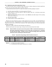
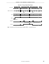
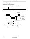
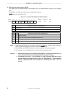
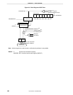
7.4.2 Operation as interval timer
When bit 4 (WDTM4) and bit 3 (WDTM3) of the watchdog timer mode register (WDTM) are set to 0 and 1,
respectively, the watchdog timer also operates as an interval timer that repeatedly generates an interrupt at time
intervals specified by a count value set in advance.
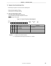
Select the count clock (or interval time) by setting bits 0 to 2 (TCL20 to TCL22) of timer clock select register 2
(TCL2). The watchdog timer starts operation as an interval timer when the RUN bit (bit 7 of WDTM) is set to 1.
In the interval timer mode, the interrupt mask flag (TMMK4) is valid, and a maskable interrupt (INTWDT) can be
generated. The priority of INTWDT is set as the highest of all the maskable interrupts.
The interval timer continues operation in the HALT mode, but stops in the STOP mode. Therefore, set RUN to 1
before entering the STOP mode to clear the interval timer, and then execute the STOP instruction.
Cautions 1. Once bit 4 (WDTM4) of WDTM is set to 1 (when the watchdog timer mode is selected), the
interval timer mode is not set, unless the RESET signal is input.
2. The interval time immediately after the setting by WDTM may be up to 0.8% shorter than
the set time.
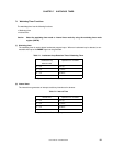
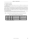
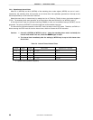
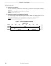
Table 7-5. Interval Time of Interval Timer
TCL22 TCL21 TCL20 Interval Time Operation at f
X
= 6.0 MHz
0002
11
× 1/f
X
341
µ
s
0102
13
× 1/f
X
1.37 ms
1002
15
× 1/f
X
5.46 ms
1102
17
× 1/f
X
21.8 ms
f
X
: System clock oscillation frequency