


CHAPTER 6 8-BIT TIMER/EVENT COUNTERS 00 AND 01
User’s Manual U12978EJ3V0UD
90
6.5 Notes on Using 8-Bit Timer/Event Counters 00 and 01
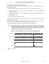
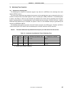
(1) Error on starting timer
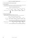
An error of up to 1 clock occurs after the timer is started until a match signal is generated. This is because 8-bit
timer counters 00 and 01 (TM00 and TM01) are started asynchronously to the count pulse.
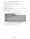
Figure 6-10. Start Timing of 8-Bit Timer Counter
Count pulse
TM00, TM01 count value
Timer starts
00H 01H 02H 03H 04H
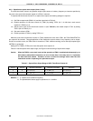
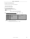
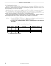
(2) Setting of 8-bit compare register
8-bit compare registers 00 and 01 (CR00 and CR01) can be set to 00H.
Therefore, one pulse can be counted when the 8-bit timer/event counter operates as an event counter.
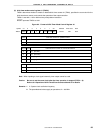
Figure 6-11. Timing of External Event Counter Operation
TI00, TI01 input
CR00, CR01 00H
TM00, TM01 count value
00H 00H 00H 00H
Interrupt request flag