


CHAPTER 9 SERIAL INTERFACE 10
User’s Manual U12978EJ3V0UD
157
9.3 Register Controlling Serial Interface 10
The following register is used to control serial interface 10.
• Serial operation mode register 10 (CSIM10)
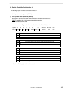
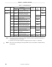
(1) Serial operation mode register 10 (CSIM10)
This register is used to control serial interface 10 and set the serial clock and start bit.
CSIM10 is set with a 1-bit or 8-bit memory manipulation instruction.
RESET input sets CSIM10 to 00H.
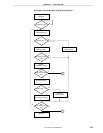
Figure 9-2. Format of Serial Operation Mode Register 10
CSIE10
0
1
Operation control in 3-wire serial I/O mode
CSIE10
00
TPS100
0 DIR10
CSCK10
0CSIM10
Symbol
Address After reset R/W
FF72H 00H R/W
<7>6543210
Operation disabled
Operation enabled
TPS100
0
1
Count clock selection when operation enabled in 3-wire serial I/O mode
f
X
/2
2
f
X
/2
3
DIR10
0
1
Start bit specification
MSB
LSB
CSCK10
0
1
Clock selection in 3-wire serial I/O mode
Clock input to SCK10 pin from external
Internal clock selected by TPS100
Caution Bits 0, 3, 5, and 6 must be set to 0.