


CHAPTER 6 8-BIT TIMER/EVENT COUNTERS 00 AND 01
User’s Manual U12978EJ3V0UD
85
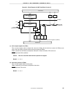
6.4 Operation of 8-Bit Timer/Event Counters 00 and 01
6.4.1 Operation as interval timer
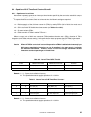
Interval timer repeatedly generates an interrupt at time intervals specified by the count value set to 8-bit compare
registers 00 and 01 (CR00 and CR01) in advance.
To operate the 8-bit timer/event counter as an interval timer, the following settings are required.
<1> Disable operation of the 8-bit timer counter 0n (TM0n) by setting TCE0n (bit 7 of 8-bit timer mode control
register 0n (TMC0n)) to 0.
<2> Set the count clock of the 8-bit timer/event counter (see Tables 6-5 and 6-6).
<3> Set count values to CR0n.
<4> Enable operation of TM0n by setting TCE0n to 1.
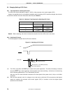
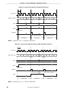
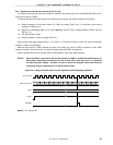
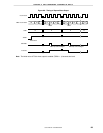
When the count value of 8-bit timer counter 0n (TM0n) matches the value set to CR0n, the value of TMn is
cleared to 0 and TM0n continues counting. At the same time, an interrupt request signal (INTTM0n) is generated.
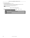
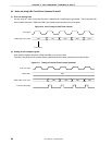
Tables 6-5 and 6-6 show the interval time, and Figures 6-6 and 6-7 show the timing of interval timer operation.
Caution When the TMC0n count clock is set and the operation of TM0n is enabled simultaneously by an
8-bit memory manipulation instruction, an error of more than 1 clock may occur in 1 cycle after
the timer has been started. Therefore, be sure to follow the settings above when the 8-bit
timer/event counter is operating as an interval timer.
Remark n = 0 or 1
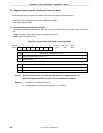
Table 6-5. Interval Time of 8-Bit Timer 00
TCL000 Minimum Interval Time Maximum Interval Time Resolution
02
6
/f
X
(10.7
µ
s) 2
14
/f
X
(2.73
µ
s) 2
6
/f
X
(10.7
µ
s)
12
9
/f
X
(85.3
µ
s) 2
17
/f
X
(21.8 ms) 2
9
/f
X
(85.3
µ
s)
Remarks 1. fX
: System clock oscillation frequency
2. The parenthesized values apply to operation at f
X
= 6.0 MHz.
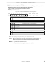
Table 6-6. Interval Time of 8-Bit Timer/Event Counter 01
TCL011 TCL010 Minimum Interval Time Maximum Interval Time Resolution
002
4
/f
X
(2.67
µ
s) 2
12
/f
X
(682.7
µ
s) 2
4
/f
X
(2.67
µ
s)
012
8
/f
X
(42.7
µ
s) 2
16
/f
X
(10.9 ms) 2
8
/f
X
(42.7
µ
s)
1 0 TI01 input cycle 2
8
× TI01 input cycle TI01 input edge cycle
1 1 TI01 input cycle 2
8
× TI01 input cycle TI01 input edge cycle
Remarks 1. fX
: System clock oscillation frequency
2. The parenthesized values apply to operation at f
X
= 6.0 MHz.