


CHAPTER 14
µ
µµ
µ
PD78F9801
User’s Manual U12978EJ3V0UD
194
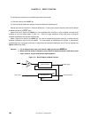
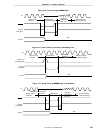
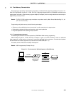
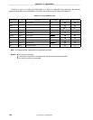
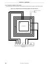
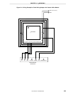
If Flashpro III (part no. FL-PR3, PG-FP3)/Flashpro IV is used as a dedicated flash programmer, the following
signals are generated for the
µ
PD78F9801. For details, refer to the manual of Flashpro III/Flashpro IV.
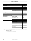
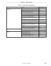
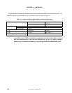
Table 14-3. Pin Connection List
Signal Name I/O Pin Function Pin Name 3-Wire Serial I/O Pseudo-3-Wire
VPP1 Output Write voltage V
PP
VPP2 −− −
×
××
××
××
×
VDD I/O V
DD
voltage generation/voltage monitoring V
DD0
, V
DD1
Note Note
GND − Ground V
SS0
, V
SS1
CLK Output Clock output X1
RESET Output Reset signal RESET
SI Input Receive signal SO10/P11
SO Output Transmit signal SI10/P12
SCK Output Transfer clock SCK10/P10
HS Input Handshake signal −
×
××
××
××
×
Note VDD
voltage must be supplied before programming is started.
Remark : Pin must be connected.
: If the signal is supplied on the target board, pin does not need to be connected.
×
××
×: Pin does not need to be connected.