


CHAPTER 5 CLOCK GENERATOR
User’s Manual U12978EJ3V0UD
75
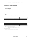
5.4 System Clock Oscillators
5.4.1 System clock oscillator
The system clock oscillator is oscillated by the crystal resonator (6.0 MHz TYP.) connected across the X1 and X2
pins.
An external clock can also be input to the circuit. In this case, input the clock signal to the X1 pin, and leave the
X2 pin open.
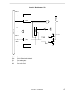
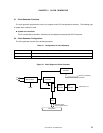
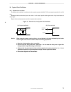
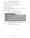
Figure 5-3 shows the external circuit of the system clock oscillator.
Figure 5-3. External Circuit of System Clock Oscillator
(a) Crystal oscillation (b) External clock
Crystal resonator
V
SS0
X2
X1
External
clock
X1
X2
OPEN
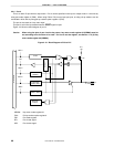
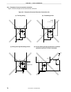
Caution When using the system clock oscillator, wire as follows in the area enclosed by the broken
lines in Figure 5-3 to avoid an adverse effect from wiring capacitance.
•
••
• Keep the wiring length as short as possible.
•
••
• Do not cross the wiring with other signal lines. Do not route the wiring near a signal line
through which a high fluctuating current flows.
•
••
• Always make the ground point of the oscillator capacitor the same potential as VSS0. Do not
ground the capacitor to a ground pattern through which a high current flows.
•
••
• Do not fetch signals from the oscillator.