


CHAPTER 4 PORT FUNCTIONS
User’s Manual U12978EJ3V0UD
71
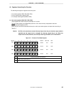
(3) Port output mode registers (POM0 and POM1)
The port output mode registers (POM0 and POM1) are used to switch from CMOS output to N-ch open-drain
output for port 0, port 1, pin P25, and pin P26.
Set POM0 and POM1 with a 1-bit or 8-bit memory manipulation instruction.
RESET input sets P0M0 and POM1 to 00H.
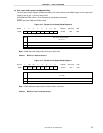
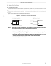
Figure 4-13. Format of Port Output Mode Register 0
Pm output mode selection
Note
(m = 0, 1)
00000
POM01POM00
POM0
Address After reset R/W
FF30H 00H R/W
765432<1><0>
POM0m
0
1
CMOS output
N-ch open-drain output
Symbol
0
Note POM0 selects the output mode for a port in 8-bit units.
Caution Bits 2 to 7 must be set to 0.
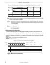
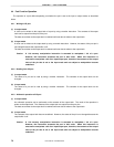
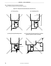
Figure 4-14. Format of Port Output Mode Register 1
Output mode selection for bit n of port 2
Note
(n = 5, 6)
0
POM126 POM125
00 00POM1
Address After reset R/W
FF31H 00H R/W
7<6><5>43210
POM12n
0
1
CMOS output
N-ch open-drain output
Symbol
0
Note POM1 selects the output mode for P25 or P26 in 1-bit units.
Caution Bits 0 to 4 and 7 must be set to 0.