


CHAPTER 12 STANDBY FUNCTION
User’s Manual U12978EJ3V0UD
183
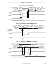
12.2.2 STOP mode
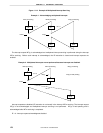
(1) Setting and operation status of STOP mode
The STOP mode is set by executing the STOP instruction.
Cautions 1. When the STOP mode is set, the X2 pin is internally pulled up to VDD to suppress the
current leakage of the crystal oscillator block. Therefore, do not use the STOP mode
in a system where an external clock is used as the system clock.
2. Because the standby mode can be released by an interrupt request signal, the standby
mode is released as soon as it is set if there is an interrupt source whose interrupt
request flag is set and interrupt mask flag is reset. When the STOP mode is set,
therefore, the HALT mode is set immediately after the STOP instruction has been
executed, the wait time set by the oscillation stabilization time select register (OSTS)
elapses, and then the operation mode is set.
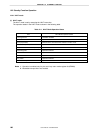
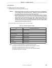
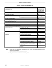
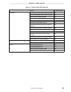
The operation status in the STOP mode is shown in the following table.
Table 12-3. STOP Mode Operation Status
Item STOP Mode Operation Status
Clock generator Oscillation disabled
CPU Operation disabled
Port (output latch) Remains in the state before the selection of STOP mode.
8-bit timer 00 (TM00) Operation disabled
8-bit timer/event counter 01 (TM01) Operation enabled
Note 1
Watchdog timer Operation disabled
USB function Operation enabled
Note 2
Serial interface 10 Operation enabled
Note 3
Key return Operation enabled
Note 4
External interrupt Operation enabled
Note 5
Notes 1. Operation is enabled only when TI01 is selected as the count clock.
2. Operation is enabled only when the USB reset or Resume signal is received.
3. Operation is enabled only when an external clock is selected.
4. Operation is enabled only for pins set in key return mode register 00 (KRM00).
5. Maskable interrupt that is not masked