


CHAPTER 16 ELECTRICAL SPECIFICATIONS
User’s Manual U12978EJ3V0UD
215
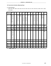
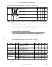
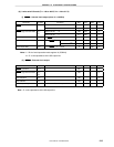
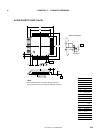
(b) 3-wire serial I/O mode (TA = −
−−
−40 to +85°
°°
°C, VDD = 4.0 to 5.5 V)
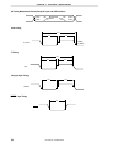
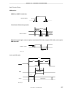
(i) SCK10 ...Internal clock output (when fX = 6.0 MHz)
Parameter Symbol Conditions MIN. TYP. MAX. Unit
When TPS100
Note 1
= 0 667 667 667 ns
SCK10 cycle time
t
KCY1
When TPS100
Note 1
= 1 1,333 1,333 1,333 ns
When TPS100
Note 1
= 0 283 333 ns
SCK10 high-/low-level width
t
KH1
,
t
KL1
When TPS100
Note 1
= 1 617 667 ns
SI10 setup time t
SIK1
To
SCK10 ↑
150 ns
When TPS100
Note 1
= 0 333 nsSI10 hold time t
KSI1
From
SCK10 ↑
When TPS100
Note 1
= 1 667 ns
SO10 output delay t
KSO1
From
SCK10 ↓, CL = 100 pF
Note 2
0 200 ns
Notes 1. Bit 4 of serial operation mode register 10 (CSIM10)
2. CL is the capacitance of the SO output line.
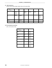
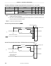
(ii)
SCK10 ...External clock output
Parameter Symbol Conditions MIN. TYP. MAX. Unit
SCK10 cycle time
t
KCY2
667 ns
SCK10 high-/low-level width
t
KH2
,
t
KL2
283 ns
SI10 setup time t
SIK2
100 ns
SI10 hold time t
KSI2
333 ns
SO10 output delay t
KSO2
From
SCK10 ↓, CL = 100 pF
Note
0 250 ns
Note CL is the capacitance of the SO output line.