


CHAPTER 8 USB FUNCTION
User’s Manual U12978EJ3V0UD
126
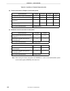
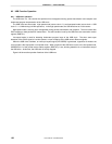
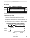
Notes 1. Be sure to follow the exact instruction sequence when the Resume signal (“K” state) is output.
SET1 REMWUP.3 ; (PULLDM ← 1)
CLR1 REMWUP.2 ; (PULLDP ← 0)
MOV A, #00000111B ; (A ← 00000111B)
SET1 REMWUP.1 ; (PULLEN ← 1)
SET1 REMWUP.0 ; (WAKEUP ← 1), “J” state output
MOV REMWUP, A ; (REMWUP ← A), “K” state output
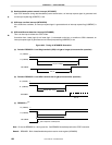
2. Be sure to follow the exact instruction sequence to append EOP when terminating Resume output.
CLR1 REMWUP.0 ; (WAKEUP ← 0) , Resume output end
CLR1 REMWUP.1 ; (PULLEN ← 0)
CLR1 REMWUP.2 ; (PULLDP ← 0)
SET1 REMWUP.3 ; (PULLDM ← 1)
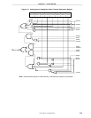
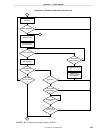
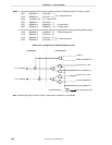
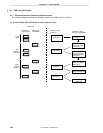
Figure 8-22. Configuration of Remote Wakeup Control
TXEN
Note
WAKEUP (REMWUP.0)
PULLDP (REMWUP.2)
Transmit data (+ side)
Transmit data (- side)
PULLDM (REMWUP.3)
PULLEN (REMWUP.1)
<Analog part> <Function part>
D+ pin (USBDP)
D- pin (USBDM)
SEP, SEM disable signal
TX MASTER EN
Note
Note Because this signal is used internally, confirmation by software is not possible.
“J” state generation
“J” state generation