


CHAPTER 14
µ
µµ
µ
PD78F9801
User’s Manual U12978EJ3V0UD
197
<RESET pin>
If the reset signal of the dedicated flash programmer is connected to the RESET pin connected to the reset signal
generator on-board, a signal conflict occurs. To prevent this, isolate the connection with the reset signal
generator.
If the reset signal is input from the user system in the flash memory programming mode, a normal programming
operation cannot be performed. Therefore, do not input reset signals from other than the dedicated flash
programmer.
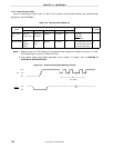
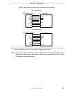
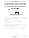
Figure 14-7. Signal Conflict (RESET Pin)
RESET
Connection pin of
dedicated flash
programmer
Reset signal generator
Signal conflict
Output pin
The signal output by the reset signal generator and the signal output from
the dedicated flash programmer conflict in the flash memory programming
mode, so isolate the signal of the reset signal generator.
PD78F9801
µ
<Port pins>
When the
µ
PD78F9801 enters the flash memory programming mode, all the pins other than those that
communicate with flash programmer are in the same status as immediately after reset.
If the external device does not recognize initial statuses such as the output high impedance status, therefore,
connect the external device to V
DD0
, V
DD1
, V
SS0
, or V
SS1
via a resistor.
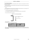
<Resonator>
When using the on-board clock, connect X1 and X2 as required in the normal operation mode.
When using the clock output of the flash programmer, connect it directly to X1, disconnecting the main resonator
on-board, and leave the X2 pin open.
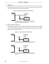
<Power supply>
To use the power output from the flash programmer, connect the V
DD0
and V
DD1
pins to VDD of the flash
programmer, and the V
SS0
and V
SS1
pins to GND of the flash programmer.
To use the on-board power supply, make connections in accordance with the normal operation mode. However,
because the voltage is monitored by the flash programmer, be sure to connect VDD of the flash programmer.
<Other pins>
Process the other pins (USBDP, USBDM, REGC) in the same manner as in the normal operation mode.