


CHAPTER 12 STANDBY FUNCTION
User’s Manual U12978EJ3V0UD
185
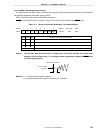
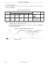
(b) Releasing by RESET input
When the STOP mode is released by the RESET signal, the reset operation is performed after the
oscillation stabilization time has elapsed.
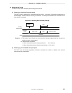
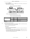
Figure 12-5. Releasing STOP Mode by RESET Input
STOP
instruction
RESET
signal
Wait
(2
15
/f
X
: 5.46 ms)
STOP mode
Operation
mode
Oscillation
stabilization
wait status
Clock
Operation
mode
Oscillation
stops
Oscillation
Oscillation
Reset
period
Remarks 1. fX
: System clock oscillation frequency
2. The parenthesized values apply to operation at 6.0 MHz.
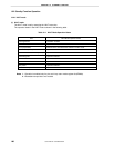
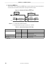
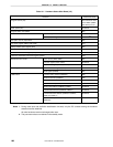
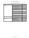
Table 12-4. Operation After Release of STOP Mode
Releasing Source MKxx IE Operation
Maskable interrupt request 0 0 Executes next address instruction
0 1 Executes interrupt servicing
1 × Retains STOP mode
RESET input ——Reset processing
×: don’t care
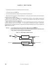
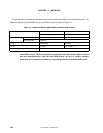
(3) Cautions an executing STOP instruction
After the STOP instruction is executed in the SE0 state (USBDM = 0, USBDP = 0), the STOP mode cannot be
released by a USB reset/Resume detection interrupt (INTUSBRE).
Therefore, the following control should be performed.
<Control method>
Do not execute the STOP instruction in the SE0 state.
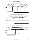
In addition, when executing the STOP instruction in the suspend mode, execute both the following two
software countermeasures.
• Do not clear the USB reset/Resume detection interrupt request flag (USBREIF) between when the
suspend state is detected and when the STOP instruction is executed.
• Clear the USB reset/Resume detection interrupt request flag (USBREIF) when the 8-bit timer that is used
as the 3 ms timer for suspend state detection is reset.