


CHAPTER 8 USB FUNCTION
User’s Manual U12978EJ3V0UD
105
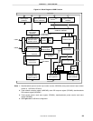
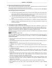
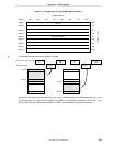
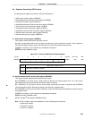
Figure 8-7. Configuration of Transmit Data Bank 1 (Buffer 1)
Data area (8 bytes)
USBPOW address
ID area
USBPOB address
USBTD1
Symbol 07H 06H 05H 04H 03H 02H 01H
USBT10
USBT11
USBT12
USBT13
USBT14
USBT15
USBT16
USBT17
30H
00H
31H
32H
33H
34H
35H
36H
37H
38H
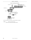
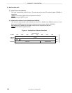
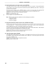
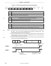
The operation during transmission appears as follows.
8th byte
1st byte USBT00
USBT07
USBT10
USBT17
.
.
.
.
.
.
.
.
.
.
.
.
.
.
.
.
.
.
IN
DATA0
ACK
Packet from host controller
Response packet
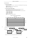
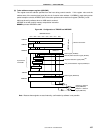
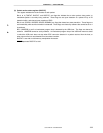
8th byte
1st byte
USBT00
USBT07
USBT10
USBT17
.
.
.
.
.
.
.
.
.
.
.
.
.
.
.
.
.
.
IN
DATA1
ACK
Data is read according to the data sequence in the control read data stage and is transmitted to the host. In the
DATA0 sequence, the values saved in USBT00 to USBT07 are transmitted in sequence to the host. In the
DATA1 sequence, the values saved in USBT10 to USBT17 are transmitted in sequence to the host.