


User’s Manual U12978EJ3V0UD
28
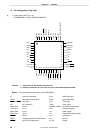
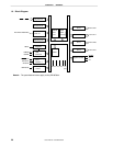
CHAPTER 2 PIN FUNCTIONS
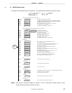
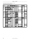
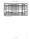
2.1 List of Pin Functions
(1) Port pins
Pin Name I/O Function After Reset Alternate
Function
P00 to P07 I/O Port 0
8-bit I/O port
Input/output can be specified in 1-bit units.
When used as an input port, use of on-chip pull-up resistors can be
specified by pull-up resistor option register 0 (PU0).
When used as an output port, CMOS output or N-ch open-drain
output can be specified in 8-bit units by port output mode register 0
(POM0).
Input —
P10 to P17 I/O Port 1
8-bit I/O port
Input/output can be specified in 1-bit units.
When used as an input port, use of on-chip pull-up resistors can be
specified by pull-up resistor option register 0 (PU0).
When used as an output port, CMOS output or N-ch open-drain
output can be specified in 8-bit units by port output mode register 0
(POM0).
Input —
P20
SCK10
P21 SO10
P22 SI10
P23 to P25 —
P26
I/O Port 2
7-bit I/O port
Input/output can be specified in 1-bit units.
When used as an input port, use of on-chip pull-up resistors can be
specified by pull-up resistor option register 0 (PU0).
When P25 or P26 is used as an output port, CMOS output or N-ch
open-drain output can be specified in 1-bit units by port output mode
register 1 (POM1).
Input
INTP0/TI01/TO01
P40 to P47 I/O Port 4
8-bit I/O port
Input/output can be specified in 1-bit units.
When used as an input port, use of on-chip pull-up resistors can be
specified by pull-up resistor option register 0 (PU0).
Input
KR00 toKR07