


CHAPTER 3 CPU ARCHITECTURE
User’s Manual U12978EJ3V0UD
42
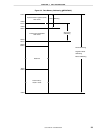
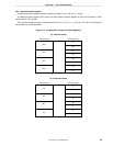
(3) Stack pointer (SP)
This is a 16-bit register that holds the start address of the memory stack area. Only the internal high-speed
RAM area can be set as the stack area.
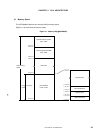
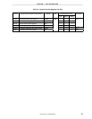
Figure 3-7. Configuration of Stack Pointer
SP15SP SP14 SP13 SP12 SP11 SP10 SP9 SP8 SP7 SP6 SP5 SP4 SP3 SP2 SP1 SP0
15 0
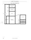
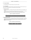
The SP is decremented ahead of write (save) to the stack memory and is incremented after read (restore) from
the stack memory.
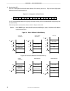
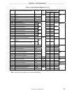
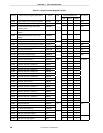
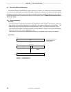
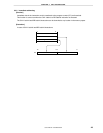
Each stack operation saves/restores data as shown in Figures 3-8 and 3-9.
Caution Since RESET input makes the SP contents undefined, be sure to initialize the SP before
instruction execution.
Figure 3-8. Data to Be Saved to Stack Memory
Interrupt
PSW
PC15 to PC8
PC15 to PC8
PC7 to PC0
Lower half
register pairs
SP SP
_
2
SP
_
2
CALL, CALLT
instructions
PUSH rp
instruction
SP
_
1
SP
SP SP
_
2
SP
_
2
SP
_
1
SP
PC7 to PC0
SP
_
3
SP
_
2
SP
_
1
SP
SP SP
_
3
Upper half
register pairs
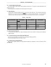
Figure 3-9. Data to Be Restored from Stack Memory
RETI instruction
PSW
PC15 to PC8
PC15 to PC8
PC7 to PC0
Lower half
register pairs
RET instructionPOP rp
instruction
SP
PC7 to PC0
Upper half
register pairs
SP + 1
SP SP + 2
SP
SP + 1
SP SP + 2
SP
SP + 1
SP + 2
SP SP + 3