


CHAPTER 16 ELECTRICAL SPECIFICATIONS
User’s Manual U12978EJ3V0UD
218
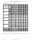
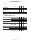
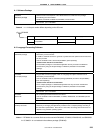
Data Memory STOP Mode Low Supply Voltage Data Retention Characteristics (TA = −
−−
−40 to +85°
°°
°C)
Item Symbol Conditions MIN. TYP. MAX. Unit
Data hold supply voltage V
DDDR
4.0 5.5 V
Release signal set time t
SREL
0
µ
s
Release by
RESET
2
15
/f
X
msOscillation stabilization
time
Note 1
t
WAIT
Release by interrupt request
Note 2
ms
Notes 1. During the oscillation stabilization time, CPU operations are disabled to prevent them from becoming
unstable upon the start of oscillation.
2. 2
12
/f
X
, 2
15
/f
X
, or 2
17
/f
X
can be selected according to the setting of bits 0 to 2 (OSTS0 to OSTS2) of the
oscillation stabilization time selection register.
Remark f
X
: System clock oscillation frequency
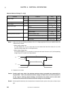
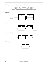
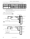
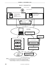
Data Hold timing (STOP Mode Release by
RESET )
VDD
Data hold mode
STOP mode
HALT mode
Internal reset operation
Operating mode
tSREL
tWAIT
STOP instruction execution
V
DDDR
RESET
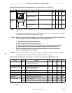
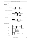
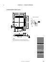
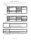
Data Hold Timing (Standby Release Signal: STOP Mode Release by Interrupt Signal)
V
DD
Data hold mode
STOP mode
HALT mode
Operating mode
t
SREL
t
WAIT
STOP instruction execution
V
DDDR
Standby release signal
(interrupt request)