


CHAPTER 16 ELECTRICAL SPECIFICATIONS
User’s Manual U12978EJ3V0UD
214
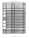
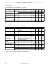
AC Characteristics
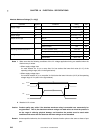
(1) Basic operations (T
A = −
−−
−40 to +85°
°°
°C, VDD = 4.0 to 5.5 V)
Parameter Symbol Conditions MIN. TYP. MAX. Unit
When PCC = 00H (f
X
= 6.0 MHz) 0.333 0.333 0.333
µ
s
Cycle time (minimum
instruction execution time)
T
CY
When PCC = 02H (f
X
= 6.0 MHz) 1.333 1.333 1.333
µ
s
TI01 input frequency f
TI
04.0MHz
TI01 input high-/low-level
width
t
TIH
, t
TIL
0.1
µ
s
Interrupt input high-/low-level
width
t
INTH
, t
INTL
INTP0 10
µ
s
RESET input low-level width
t
RSL
10
µ
s
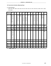
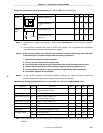
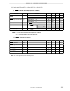
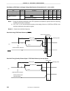
(2) Serial interface
(a) USB function (T
A = 0 to +70°
°°
°C, VDD = 4.0 to 5.5 V)
Parameter Symbol Conditions MIN. TYP. MAX. Unit
CL = 50 pF
Note
75 nsUSBDM and USBDP rise time t
R
CL = 350 pF
Note
300 ns
CL = 50 pF
Note
75 nsUSBDM and USBDP fall time t
F
CL = 350 pF
Note
300 ns
t
R
and t
F
matching t
RFM
t
R
/t
F
80 120 %
Differential output signal
cross-over point
V
CRS
1.3 2.0 V
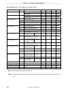
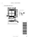
Data transfer rate t
DRATE
When the microcontroller operates at the
system clock (f
X
) of 6.0 MHz
1.5 1.5 1.5 Mbps
t
UDJ1
Upon transferring the next bit
−95
095nsTransmission differential
signal jitter
t
UDJ2
Upon transferring the bit following the next bit
−150
0 150 ns
Transmission EOP width t
EOPT1
1.25 1.33 1.50
µ
s
t
EOPR1
EOP width to be eliminated 300
µ
s
Reception EOP width
tEOPR2
EOP width to be detected 675
µ
s
t
URES1
USB reset width to be eliminated 2.5
µ
s
Reception USB reset width
tURES2
USB reset width to be detected 5.5
µ
s
Note CL is the capacitance of the USBDM and USBDP output lines.