


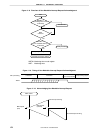

CHAPTER 11 INTERRUPT FUNCTIONS
User’s Manual U12978EJ3V0UD
168
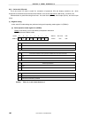
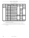
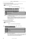
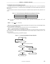
(2) Interrupt mask flag registers (MK0 and MK1)
The interrupt mask flag is used to enable/disable the corresponding maskable interrupt servicing.
MK0 and MK1 are set with a 1-bit or 8-bit memory manipulation instruction.
RESET input sets MK0 and MK1 to FFH.
Figure 11-3. Format of Interrupt Mask Flag Register
0
1
Interrupt servicing control
Interrupt servicing enabled
Interrupt servicing disabled
XXMKX
MK1 FFE5H FFH R/W
TMMK01TMMK00
CSIMK10
KRMK00 1 1 PMK0 TMMK4MK0
R/W
FFE4H FFH R/W
0
USBTMMKUSBRTMKUSBRDMKUSBSTMK
USBREIF
11
Symbol
Address After reset
<6> <5> <4> 3 2 <1><7> <0>
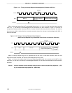
<6> <5> <4> <3> <2> 170
Cautions 1. If the TMMK4 flag is read when the watchdog timer is used in watchdog timer mode 1
or 2, its value becomes undefined.
2. Because port 2 has an alternate function as an external interrupt input, when the
output level is changed by specifying the output mode of the port function, an
interrupt request flag is set. Therefore, the interrupt mask flag should be set to 1
before using the output mode.
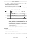
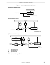
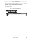
(3) External interrupt mode register 0 (INTM0)
This register is used to set the valid edge of INTP0.
INTM0 is set with an 8-bit memory manipulation instruction.
RESET input sets INTM0 to 00H.
Figure 11-4. Format of External Interrupt Mode Register 0
Cautions 1. Bits 0, 1 and 4 to 7 must be set to 0.
2. Before setting the INTM0 register, be sure to set xxMKx of the relevant interrupt mask
flag to 1 to disable interrupts. After that clear the interrupt mask flag (xxMKx = 0) to
enable interrupts after clearing the interrupt request flag(xxIFx = 0).
0
0
1
1
0000ES01 ES00 0 0INTM0
R/W
FFECH 00H R/W
76543210
0
1
0
1
Symbol
Address After reset
INTP0 valid edge selection
Falling edge
Rising edge
Setting prohibited
Both rising and falling edges
ES00
ES01