


CHAPTER 7 WATCHDOG TIMER
User’s Manual U12978EJ3V0UD
94
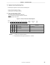
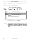
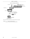
(2) Watchdog timer mode register (WDTM)
This register sets the operation mode of the watchdog timer, and enables/disables counting of the watchdog
timer.
The WDTM is set with a 1-bit or 8-bit memory manipulation instruction.
RESET input sets the WDTM to 00H.
Figure 7-3. Format of Watchdog Timer Mode Register
RUN
0
1
Selection of operation of watchdog timer
Note 1
RUN 0 0
WDTM4 WDTM3
000WDTM
Symbol
Address After reset R/W
FFF9H 00H R/W
<7>6543210
Stop counting
Clear counter and start counting
WDTM4
Selection of operation mode of watchdog timer
Note 2
WDTM3
0
1
1
0
1
1
Operation disabled
Interval timer mode (overflow and maskable interrupt occur)
Note 3
Watchdog timer mode 1 (overflow and non-maskable interrupt occur)
Watchdog timer mode 2 (overflow occurs and reset operation started)
0
0
Notes 1. Once RUN has been set (1), it cannot be cleared (0) by software. Therefore, when counting is
started, it cannot be stopped by any means other than RESET input.
2. Once WDTM3 and WDTM4 have been set (1), they cannot be cleared (0) by software.
3. The watchdog timer starts operations as an interval timer when RUN is set to 1.
Cautions 1. When the watchdog timer is cleared by setting RUN to 1, the actual overflow time is up
to 0.8% shorter than the time set by timer clock select register 2 (TCL2).
2. In watchdog timer mode 1 or 2, set WDTM4 to 1 after confirming TMIF4 (bit 0 of the
interrupt request flag register 0 (IF0)) is set to 0. While TMIF4 is 1, a non-maskable
interrupt is generated upon write completion if watchdog timer mode 1 or 2 is
selected.