


CHAPTER 8 USB FUNCTION
User’s Manual U12978EJ3V0UD
113
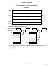
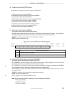
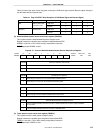
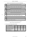
Table 8-2 shows the state of each flag after receiving the USB reset signal and the Resume signal during the
bus idle state and bus suspend state.
Table 8-2. Flag of RXSTAT After Reception of USB Reset Signal and Resume Signal
Bus State Device State Received Signal RESMRX SE0RX URESRX
USB reset 0 1 1Idle Main system clock
operation mode
Resume 1 1 0
USB reset 0 1 1Suspend STOP mode
Resume 1 1 0
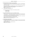
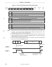
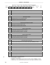
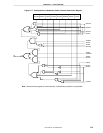
(4) Data/handshake packet receive result store register (DRXRSL)
This register stores the data/handshake packet reception result.
Register contents are updated upon reception of data/handshake EOP.
DRXRSL is set with a 1-bit or 8-bit memory manipulation instruction.
RESET input sets DRXRSL to 00H.
Figure 8-13. Format of Data/Handshake Packet Receive Result Store Register
Symbol <6><7> <5> 4 3 2 <1> 0
CR16ER DBITER DBYER 0 0 0 DIDRST 0
CR16ER CRC error detection (16-bit mode)
0
1
FF65H
Address
DRXRSL
After reset
00H
R/W
R/W
CRC error did not occur in received data packet.
CRC error occurred in received data packet.
DBITER Bit stuffing error detection
0
1
Bit stuffing error did not occur in received data/handshake packet.
Bit stuffing error occurred in received data/handshake packet.
DBYER Received data/handshake packet length error detection
0
1
Packet length of received data/handshake packet is normal.
Packet length of received data/handshake packet is abnormal.
DIDRST Data/handshake packet ID comparison result
0
1
Received data/handshake
packet
ID and value of data/handshake
PID
compare register (DIDCMP)
do not match.
Received data/handshake
packet
ID and value of DIDCMP match.
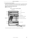
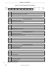
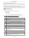
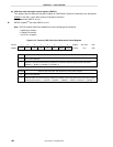
(5) Token packet receive result store register (TRXRSL)
This register stores the token packet reception status.
Register contents are updated upon reception of token packet EOP.
TRXRSL is set with a 1-bit or 8-bit memory manipulation instruction.
RESET input sets TRXRSL to 00H.