


CHAPTER 7 WATCHDOG TIMER
User’s Manual U12978EJ3V0UD
92
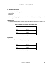
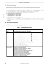
7.2 Watchdog Timer Configuration
The watchdog timer consists of the following hardware.
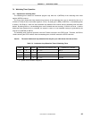
Table 7-3. Configuration of Watchdog Timer
Item Configuration
Control register Timer clock select register 2 (TCL2)
Watchdog timer mode register (WDTM)
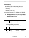
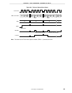
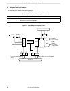
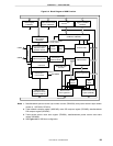
Figure 7-1. Block Diagram of Watchdog Timer
Internal bus
Internal bus
Prescaler
Selector
Controller
f
X
2
6
f
X
2
8
f
X
2
10
3
7-bit counter
Clear
TMIF4
TMMK4
TCL22 TCL21 TCL20
Timer clock select register 2
(TCL2)
Watchdog timer mode register (WDTM)
WDTM4 WDTM3
INTWDT
maskable
interrupt request
RESET
INTWDT
non-maskable
interrupt request
f
X
2
4
RUN