


CHAPTER 6 8-BIT TIMER/EVENT COUNTERS 00 AND 01
User’s Manual U12978EJ3V0UD
81
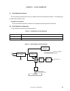
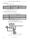
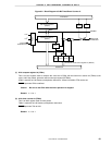
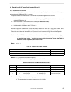
Figure 6-2. Block Diagram of 8-Bit Timer/Event Counter 01
Internal bus
8-bit compare register 01
(CR01)
Match
TO01/P26/
INTP0/TI01
INTTM01
f
X
/2
4
f
X
/2
8
TI01/P26
/INTP0/TO01
Selector
Clear
8-bit timer counter 01
(TM01)
2
Internal bus
TCE01 TCL011 TCL010 TOE01
8-bit timer mode control register 01 (TMC01)
F/F
P26
Output latch
PM26
Selector
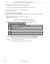
(1) 8-bit compare register 0n (CR0n)
This is an 8-bit register used to compare the value set to CR0n with the 8-bit timer counter 0n (TM0n) count
value, and if they match, generate used an interrupt request (INTTM0n).
CR0n is set with an 8-bit memory manipulation instruction. Values from 00H to FFH can be set.
RESET input sets CR0n undefined.
Caution Be sure to set CR0n after the timer operation is stopped.
Remark n = 0 or 1
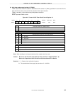
(2) 8-bit timer counter 0n (TM0n)
This is an 8-bit register used to count pulses.
TM0n is read with an 8-bit memory manipulation instruction.
RESET input sets TMn to 00H.
Remark n = 0 or 1