


CHAPTER 1 GENERAL
User’s Manual U12978EJ3V0UD
22
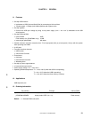
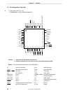
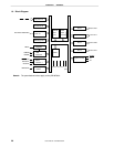
1.4 Pin Configuration (Top View)
• 44-pin plastic LQFP (10 × 10)
µ
PD789800GB-×××-8ES,
µ
PD78F9801GB-8ES
P04
P03
P02
P01
P00
VDD1
VSS1
P17
P16
P15
P14
NC
P13
P12
P11
P10
P47/KR07
P46/KR06
P45/KR05
P44/KR04
P43/KR03
P42/KR02
USBDP
USBDM
IC (V
PP)
REGC
V
DD0
VSS0
X1
X2
RESET
P40/KR00
P41/KR01
P05
P06
P07
P20/SCK10
P21/SO10
P22/SI10
P23
NC
P24
P25
P26/TI01/TO01/INTP0
44 43 42 41 40 39 38 37 36 35 34
12 13 14 15 16 17 18 19 20 21 22
1
2
3
4
5
6
7
8
9
10
11
33
32
31
30
29
28
27
26
25
24
23
Cautions 1. Connect the IC pin directly to the VSS0 pin.
2. Directly connect the VPP pin to the VSS0 pin in the normal operation mode.
Remark The parenthesized values apply to the
µ
PD78F9801.
IC: Internally connected SI10: Serial data input
INTP0: Interrupt from peripherals SO10: Serial data output
KR00 to KR07 :
Key return TI01: Timer input
NC: No connection TO01: Timer output
P00 to P07: Port 0 USBDM, USBDP: Universal serial bus data
P10 to P17: Port 1 VDD0
: Port power supply
P20 to P26: Port 2 V
DD1
: Power supply
P40 to P47: Port 4 V
PP
: Programming power supply
RESET : Reset V
SS0
: Port ground
REGC: Voltage regulator for USB function VSS1
: Ground
SCK10 : Serial clock input/output X1, X2: Crystal