


CHAPTER 8 USB FUNCTION
User’s Manual U12978EJ3V0UD
148
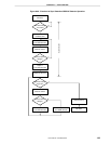
8.8.3 Sync detection/USBCLK detector operation
This circuit generates the USBCLK signal (1.5 MHz) upon detecting the sync part of the receive packet. In
addition, it contains an NRZI decoder that decodes receive packets and detects the last bit of the sync part.
When the last sync bit is detected, a signal that specifies start of storing in the ID detection buffer is output.
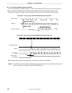
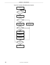
Figure 8-27. Timing of Sync Detection/USBCLK Detector Operation
Receive packet
USBCLK
USBCLK generation
NRZI decode
Data after decoding
SYNC last bit detection
SYNC pattern
After token packet
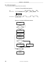
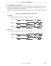
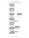
Figure 8-28. Timing of Sync Detection/USBCLK Generation Operation
f
X
USBCLK
Receive data
(RXD)
Resume RX
Note
(INTUSBRE)
TX MASTER EN
Note
SyncIdle
L
10101011100
Note Because these signals are used internally, confirmation by software is not possible.
Remark The USB clock starts operating at the falling edge of fX
after transition from the J state to the K state of
the bus. However, this control is masked if TX MASTER EN = 1.