1-8
Section 1 — System Overview
Video and Key Inputs and Outputs
Inputs
Two types of input modules may be installed in the Signal
Processor Frame to suit the needs of your installation. The
following types of input modules are available.
NOTE:
Each of the serial or analog inputs can be treated by the switcher
as either a video input or a key input.
■
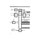
Serial Digital Input Module – provides 8 inputs, auto-timed
within a range of ±18 microseconds. Two modules are
supplied in the standard configuration. Two modules are
available as options. With four modules installed there are 32
inputs available.The modules are located in Bay C.
■
Chroma Key Input Modules (optional) – Either one or two
Chroma Key Input Modules may be configured. These
modules allow full bandwidth chroma keys. Each module has
two inputs. Each input has three BNC connectors labeled:
G/V, B/U, and R/V. There is a separate gain adjustment near
each BNC connector. The format for each input is user-
selectable from RGB, YUV, Beta or MII. The module is located
in Bay C.
Refer to the
Model 2200 Installation and Service
manual, Section 3,
Functional Description, for more information.
Refer to the
Model 2200 User Guide
for information on assigning
input formats and adjusting the timing.


