


2-42
Section 2— Startup and Configuration
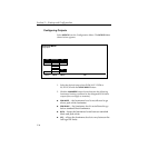
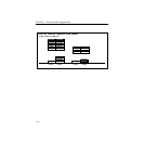
DPM Configurations
Digital Picture Manipulators (DPMs) are external video devices
connected to the switcher. In this discussion, reference is also
made to DPM levels, which are E-MEM levels into which DPM-
associated information is learned. The combined system
capabilities of the switcher and DPMs depend on:
■ The video connection
■ The capabilities of the DPM
■ The control connection
It is not necessary to have a control connection from the switcher
to a DPM; however, the highest level of system integration is
achieved where there is a control connection.
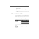
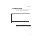
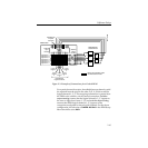
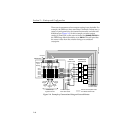
The Video Connection (Aux Buses and Return Inputs)
A normal video signal path consists of an aux bus output from the
switcher feeding a DPM input and the DPM output returned to a
switcher input which is mapped to a switcher source select
button.
The video path through a DPM introduces a video delay into the
system. For example, Kaleidoscope introduces a 2-field video
delay.
NOTE:
If the video delay is not set correctly, there will be a glitch in the
video upon entering Effects Send mode.
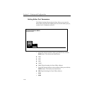
There are four steps in configuring the video path:
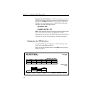
■ Aux buses are assigned to DPMs using the DPM Map Aux
Buses Menu
■ Return input connections are configured using the DPM Map
Inputs Menu
■ The mapping of a return connection to a crosspoint is done
using the Configuration/Map Inputs Menu
■ The video delay is set using the DPM Setup Menu