


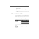

2-45
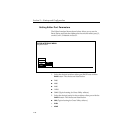
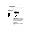
Software Setup
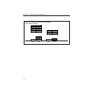
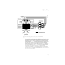
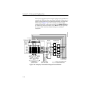
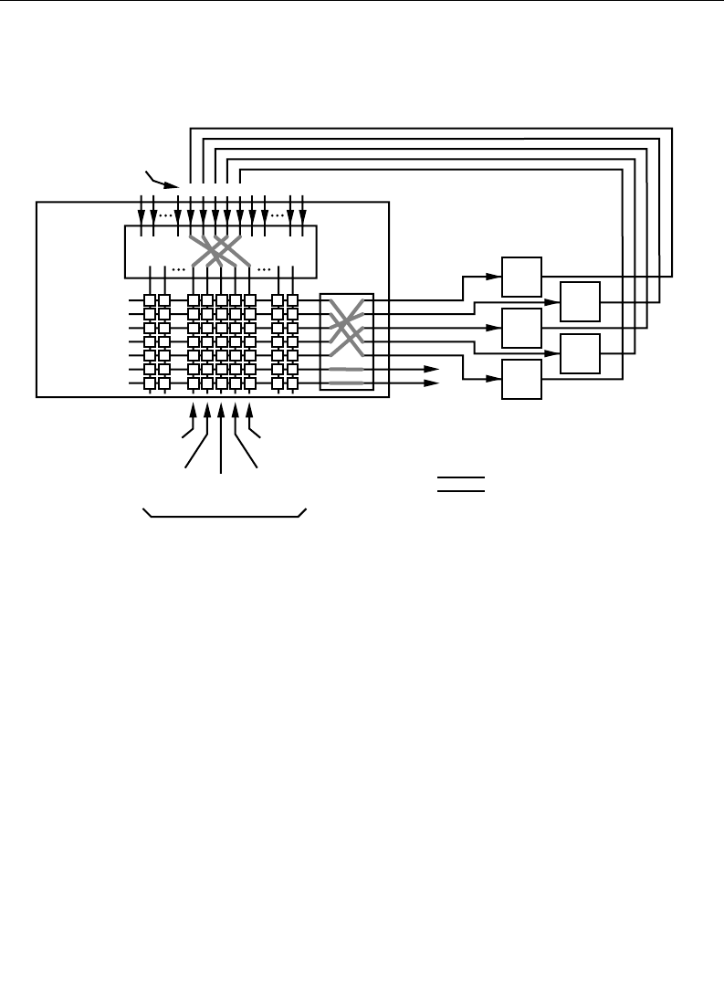
For a particular studio session, three Kaleidoscope channels could
be acquired from the pool in the order D, E, A, which would be
logical channels 1, 2, 3. This mapping information is passed from
the DPM to the switcher via the control connection. Switcher
output routing ensures that the logical channels 1, 2, 3 appear to
the user on logical aux buses 1, 2, 3 and switcher input routing
ensures that DPM logical channels 1, 2, 3 appear on the
crosspoints configured for these logical channels. For the above
configuration, the selection of CHANNEL ROUTING in the DPM Setup
Menu should be set to BOTH.
Figure 2-3. Example of Connections for a Pooled DPM
Kaleidoscope
Logical Channels
Effects Send Capable Video
Non-Effects Send Video
Kaleidoscope
Channel Pool
Switcher
Output
Routing
Phys Aux 2
Phys Aux 1
Phys Aux 3
Phys Aux 4
Phys Aux 5
Switcher
Input
Routing
Kaleidoscope
Physical
Channels
Logical Aux 1
Logical Aux 7
Logical Aux 4
Logical Aux 6
Logical Aux 5
Logical Aux 3
Logical Aux 2
A
C
E
B
D
Model 4000
Logical
Channel
2
Logical
Channel
5
Logical
Channel
4
Logical
Channel
3
Logical
Channel
1
0347-02-29
EDCBA