


AT-9000 Switch Command Line User’s Guide
247
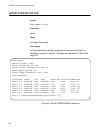
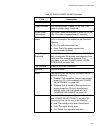
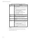
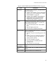
Table 23. SHOW POWER-INLINE Command
Field Description
Nominal Power The switch’s total available power in watts (W).
Power Allocated The available power in watts (W) for PDs. This
value is updated every 5 seconds.
Actual Power
Consumption
The current power consumption in watts (W) of the
PDs. This value is updated every 5 seconds.
Operational
Status
The operational status of the power supply units
(PSU) in the switch. The status can be one of the
following:
On: The units are powered on.
Fault: One of the power supplies has
encountered a problem.
Power Usage
Threshold
The SNMP power-inline trap threshold. A SNMP
trap is transmitted if the power requirements of the
switch and PDs exceed the threshold. This
parameter is set with “POWER-INLINE USAGE-
THRESHOLD” on page 244.
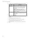
PoE Interface A table of port PoE information.
Interface The port number.
Admin The status of PoE on the port. The status can be
one of the following:
Enabled: PoE is enabled. The port can transmit
power to a PD. PoE is enabled with “POWER-
INLINE ENABLE” on page 240.
Disabled: PoE is disabled. The port does not
supply power to a PD, but it does forward
network traffic. PoE is disabled with “NO
POWER-INLINE ENABLE” on page 232.
Pri The port’s PoE priority level. This parameter is set
with “POWER-INLINE PRIORITY” on page 242.
The priority level can be one of the following:
Low: The lowest priority level. Default level.
High: The higher priority level.
Crit: Critical, the highest priority level.