


AT-9000 Switch Command Line User’s Guide
643
Multiple Spanning Tree Instance (MSTI)
The individual spanning trees in MSTP are referred to as Multiple
Spanning Tree Instances (MSTIs). An MSTI can span any number of AT-
9000 Switches. The switch can support up to 15 MSTIs at a time.
To create an MSTI, you first assign it a number, referred to as the MSTI ID.
The range is 1 to 15. (The switch is shipped with a default MSTI with an
MSTI ID of 0. This default spanning tree instance is discussed later in
“Common and Internal Spanning Tree (CIST)” on page 651.)
After you have selected an MSTI ID, you need to define the scope of the
MSTI by assigning one or more VLANs to it. An instance can contain any
number of VLANs, but a VLAN can belong to only one MSTI at a time.
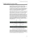
Following are several examples. Figure 122 illustrates two AT-9000
Switches, each containing the two VLANs Sales and Production. The two
parts of each VLAN are connected with a direct link using untagged ports
on both switches. If the switches were running STP or RSTP, one of the
links would be blocked because the links constitute a physical loop. Which
link would be blocked depends on the STP or RSTP bridge settings. In
Figure 122, the link between the two parts of the Production VLAN is
blocked, resulting in a loss of communications between the two parts of
the Production VLAN.
Figure 122. VLAN Fragmentation with STP or RSTP
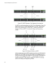
Figure 123 illustrates the same two AT-9000 Switches and the same two
virtual LANs. But in this example, the two switches are running MSTP, and
the two VLANs have been assigned different spanning tree instances.
Now that they reside in different MSTIs, both links remain active, enabling
the VLANs to forward traffic over their respective direct link.