1
Figures
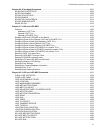
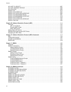
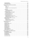
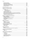
Figure 1: Command Modes ................................................................................................................................................. 21
Figure 2: ENABLE Command.............................................................................................................................................. 24
Figure 3: CONFIGURE TERMINAL Command................................................................................................................... 24
Figure 4: LINE CONSOLE Command ................................................................................................................................. 24
Figure 5: LINE VTY Command............................................................................................................................................ 25
Figure 6: INTERFACE TRUNK Command .......................................................................................................................... 25
Figure 7: INTERFACE PORT Command - Single Port........................................................................................................ 25
Figure 8: INTERFACE PORT Command - Multiple Ports.................................................................................................... 26
Figure 9: INTERFACE PORT Command - Moving Between Port Interface Modes ............................................................ 26
Figure 10: INTERFACE TRUNK Command ........................................................................................................................ 26
Figure 11: INTERFACE VLAN Command........................................................................................................................... 26
Figure 12: VLAN DATABASE Command ............................................................................................................................ 27
Figure 13: LLDP LOCATION CIVIC-LOCATION Command ............................................................................................... 27
Figure 14: LLDP LOCATION COORD-LOCATION Command............................................................................................ 27
Figure 15: Moving Up One Mode with the EXIT and QUIT Command................................................................................ 28
Figure 16: Returning to the Privileged Exec Mode with the END Command....................................................................... 29
Figure 17: Returning to the User Exec Mode with the DISABLE Command....................................................................... 29
Figure 18: PORT Parameter in the Command Line Interface.............................................................................................. 30
Figure 19: Startup Messages .............................................................................................................................................. 34
Figure 20: Startup Messages (continued)............................................................................................................................ 35
Figure 21: Startup Messages (continued)............................................................................................................................ 36
Figure 22: Connecting the Management Cable to the Console Port................................................................................... 38
Figure 23: AlliedWare Plus Command Line Prompt ............................................................................................................ 39
Figure 24: SHOW BOOT Command.................................................................................................................................... 43
Figure 25: Displaying the Keywords of a Mode ................................................................................................................... 51
Figure 26: Displaying Subsequent Keywords of a Keyword................................................................................................ 51
Figure 27: Displaying the Class of a Parameter .................................................................................................................. 52
Figure 28: SHOW SYSTEM ENVIRONMENT Command ................................................................................................... 75
Figure 29: SHOW ECOFRIENDLY Command.................................................................................................................... 80
Figure 30: SHOW SYSTEM ENVIRONMENT Command ................................................................................................... 81
Figure 31: SHOW BOOT Command.................................................................................................................................... 92
Figure 32: SHOW BAUD-RATE Command......................................................................................................................... 94
Figure 33: Banner Messages .............................................................................................................................................. 99
Figure 34: HELP Command............................................................................................................................................... 116
Figure 35: SHOW BANNER LOGIN Command................................................................................................................. 127
Figure 36: SHOW BAUD-RATE Command....................................................................................................................... 128
Figure 37: SHOW SWITCH Command.............................................................................................................................. 131
Figure 38: SHOW SYSTEM Command............................................................................................................................. 133
Figure 39: SHOW SYSTEM SERIALNUMBER Command................................................................................................ 134
Figure 40: SHOW USERS Command ............................................................................................................................... 135
Figure 41: SHOW VERSION Command............................................................................................................................ 137
Figure 42: SHOW FLOWCONTROL INTERFACE Command .......................................................................................... 151
Figure 43: SHOW STORM-CONTROL Command............................................................................................................ 156
Figure 44: SHOW STORM-CONTROL Command............................................................................................................ 156
Figure 45: SHOW INTERFACE STATUS Command ........................................................................................................ 159
Figure 46: SHOW INTERFACE Command ....................................................................................................................... 160
Figure 47: SHOW RUNNING-CONFIG INTERFACE Command ...................................................................................... 160
Figure 48: Head of Line Blocking ...................................................................................................................................... 180
Figure 49: SHOW FLOWCONTROL INTERFACE Command .......................................................................................... 191


