


AT-9000 Switch Command Line User’s Guide
517
Source MAC Address / Destination MAC Address (Layer 2)
Source IP Address (Layer 3)
Destination IP Address (Layer 3)
Source IP Address / Destination IP Address (Layer 3)
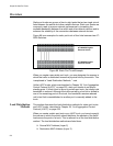
The load distribution methods examine the last three bits of a packet’s
MAC or IP address and compare the bits against mappings assigned to
the ports in the trunk. The port mapped to the matching bits is selected as
the transmission port for a packet.
In cases where you select a load distribution that employs either a source
or destination address but not both, only the last three bits of the
designated address are used in the selection process. If you select one of
the two load distribution methods employing both source and destination
addresses, port selection is achieved through an XOR operation of the last
three bits of both addresses.
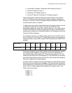
For example, assume you created a static port trunk or an LACP trunk of
Ports 7 through 14 on the switch. The table below shows the mappings of
the switch ports to the possible values of the last three bits of a MAC or IP
address.
Assume you selected source MAC address as the load distribution method
and that the switch needed to transmit over the trunk a packet with a
source MAC address that ended in 9. The binary equivalent of 9 is 1001,
making the last three bits of the address 001. An examination of the table
above indicates that the switch uses Port 8 to transmit the frame because
that port is mapped to the matching bits.
A similar method is used for the two load distribution methods that employ
both the source and destination addresses. Only here the last three bits of
both addresses are combined by an XOR process to derive a single value
which is then compared against the mappings of the bits to ports. The
XOR rules are as follows:
0 XOR 0 = 0
0 XOR 1 = 1
1 XOR 0 = 1
1 XOR 1 = 0
Last 3 Bits 000
(0)
001
(1)
010
(2)
011
(3)
100
(4)
101
(5)
110
(6)
111
(7)
Trunk Ports 7891011121314