


AT-9000 Switch Command Line User’s Guide
695
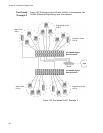
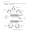
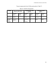
The table below lists the port assignments for the Sales, Engineering, and
Production VLANs on the switches:
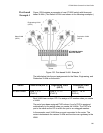
Sales VLAN - This VLAN spans both switches. It has a VID value
of 2 and consists of six untagged ports on the top switch and five
untagged ports on the bottom switch.
The two parts of the VLAN are connected by a direct link from port
4 on the top switch to port 3 on the bottom switch. This direct link
allows the two parts of the Sales VLAN to function as one logical
LAN segment.
Port 6 on the top switch connects to the router. This port allows the
Sales VLAN to exchange Ethernet frames with the other VLANs
and to access the WAN.
Engineering VLAN - The workstations of this VLAN are connected
to ports 9 to 13 on the top switch and ports 16, 18 to 20, and 22 on
the bottom switch.
Because this VLAN spans multiple switches, it needs a direct
connection between its various parts to provide a communications
path. This is provided in the example with a direct connection from
port 10 on the top switch to port 19 on the bottom switch.
This VLAN uses port 12 on the top switch as a connection to the
router and the WAN.
Production VLAN - This is the final VLAN in the example. It has the
VLAN of 4, and its ports have been assigned the PVID also of 4.
The nodes of this VLAN are connected only to the top switch. So
this VLAN does not require a direct connection to the bottom
switch. However, it uses port 20 as a connection to the router.
Switch Sales VLAN
(VID 2)
Engineering VLAN
(VID 3)
Production VLAN
(VID 4)
AT-9000 Switch
(top)
Ports 1 - 6
(PVID 2)
Ports 9 - 13
(PVID 3)
Ports 17, 19 - 21
(PVID 4)
AT-9000 Switch
(bottom)
Ports 2 - 4, 6, 8
(PVID 2)
Ports 16, 18-20, 22
(PVID 3)
none