


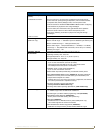
CV7 Touch Panel Accessories
9
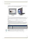
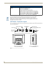
7" Modero Widescreen Touch Panels
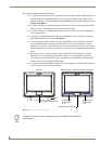
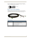
Use a standard CAT5 Ethernet cable to provide both communication and 10/100 network connectivity
between the panel, NXA-AVB/ETHERNET, NetLinx Master, and the network.
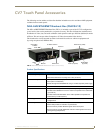
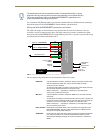
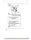
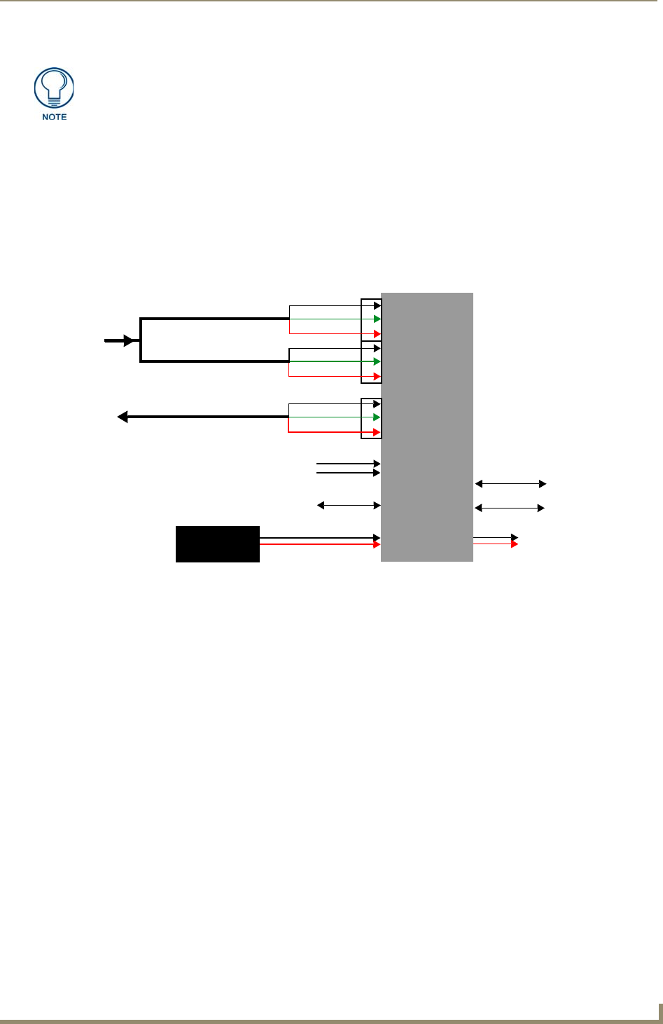
Wiring the NXA-AVB/ETHERNET connectors and cables
The inputs and outputs on the breakout box are separated into front and rear connectors. The rear
connectors are used to input external signals. The front connectors are used to communicate signals
between the NXA-AVB/ETHERNET and a target Modero panel. FIG. 7 provides a layout of the wiring
connection both into and from the breakout box.
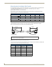
The rear-panel wiring connections are described below (from left to right):
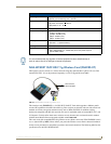
The breakout box unit can be mounted on either a horizontal flat surface or into an
equipment rack (by removing the front screws and attaching it to an optional AC-RK).
The power supply being used on the NXA-AVB/ETHERNET is dependant on the
power requirements of the target touch panel.
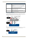
FIG. 7 NXA-AVB/ETHERNET Breakout Box connector wiring diagram
• AUDIO IN: 6-pin mini-Phoenix connector, divided into left and right audio channels. Each
channel is divided into GND, IN+, and IN- terminal cable connectors
(2 sets of 3 for each channel).
An example of this cable is to strip the ends of 2 RCA audio cables and insert
them into their respective locations on the Audio In port.
Either a balanced (+, -, and GND) or unbalanced (+ and GND) audio
signal can be connected to this input.
• MIC OUT: 4-pin mini-Phoenix connector, divided into GND, OUT-, and OUT+ terminal
connectors.
An example of this cable is to strip the terminal ends of a 3.5mm mini-jack and
insert them into their respective locations on the Mic Out port. This signal can
be fed as a Line Level In to either an amplifier or an AMX VOL card.
Either a balanced (+, -, and GND) or unbalanced (+ and GND) audio signal
can be connected to this output.
• Video In BNCs: Feeds either Composite/S-Video Luma or S-Video Chroma signals into the
NXA-AVB/ETHERNET. This feed is then redirected out to a Modero panel
through the front Audio/Video CAT5 port.
• ETHERNET: RJ-45 connector routes data to the G4 touch panel through the front Ethernet
port. These connections use a standard CAT5 Ethernet cable to provide
communication between the target touch panel, breakout box, and NetLinx
Master.
NXA-AVB/ETHERNET
Breakout Box
Ethernet
(RJ-45)
Audio In - Left Channel
(6-pin captive wire)
Audio In - Right Channel
(6-pin captive wire)
GND
In (-)
In (+)
GND
In (-)
In (+)
GND(-)
Out (-)
Out (+)
Microphone Out
(4-pin captive wire)
12 VDC power
Ethernet Out
(CAT5)
Audio/Video
(CAT5)
Power to
touch panel
F
R
O
N
T
R
E
A
R
supply
Comp/Y (BNC)
C (BNC)