


CV7 Touch Panel Accessories
29
7" Modero Widescreen Touch Panels
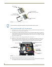
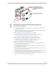
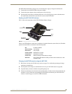
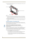
4. Carefully angle the NXT-CV7 panel over the front alignment pegs (FIG. 29). The pegs assist in both
aligning and securing the panel to the base (the locking mechanism secures the base to panel when
done).
5. Insert the alignment pegs into their corresponding holes below the front of the panel.
6. Verify the alignment of the Panel Interface connectors between the panel (female connector) and
base (male connector) (FIG. 29).
7. Align the rear pegs and gently push the rear of the panel downwards until it is mounted atop the
battery base.
8. Slide the rear battery locking slider in the opposite direction. This turns the latching mechanism and
secures the panel to the base.
9. Upon successful connection, the AMX logo appears on the panel to indicate that the panel is
properly connected and receiving power.
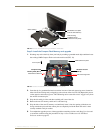
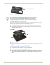
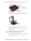
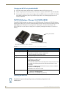
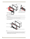
FIG. 28 NXA-BASE/1 showing Panel Interface and connector locations
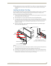
FIG. 29 NXA-BASE/1 shown aligning with NXT-CV7 panel
Panel Interface
connector (male)
Securing
pegs (2)
Front
Back
Battery
locking
mechanism
Battery
locking slider
Insert holes for
NXT-CV7 feet
Alignment
pegs (2)
(Battery not shown
for illustration purposes)
Alignment
pegs
Battery
locking
mechanism
(with locking
slider)
The battery base CANNOT be hot-swapped. An NXT can not be receiving power
(through a connected power supply) and then be connected to a battery base.
Always POWER OFF the panel before installing the NXA-BASE/1.