


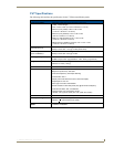
CV7 Touch Panel Accessories
10
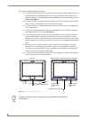
7" Modero Widescreen Touch Panels
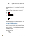
Wiring the NXA-AVB/ETHERNET for Unbalanced Audio
Most domestic audio equipment has unbalanced audio inputs and outputs. This means that the audio
output (left, right, or mono) appears on a single wire, and is referenced to "0 V" or "Ground". Typical
connectors used are RCA "phono" connectors, DIN plugs/sockets, and 0.25" (6.3mm) or 3.5mm jack
plugs/sockets.
Unbalanced audio is adequate for most domestic environments and for line-level signals in a typical
broadcast studio. Problems may occur if the signals are carried over long distances, especially if the
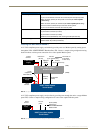
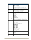
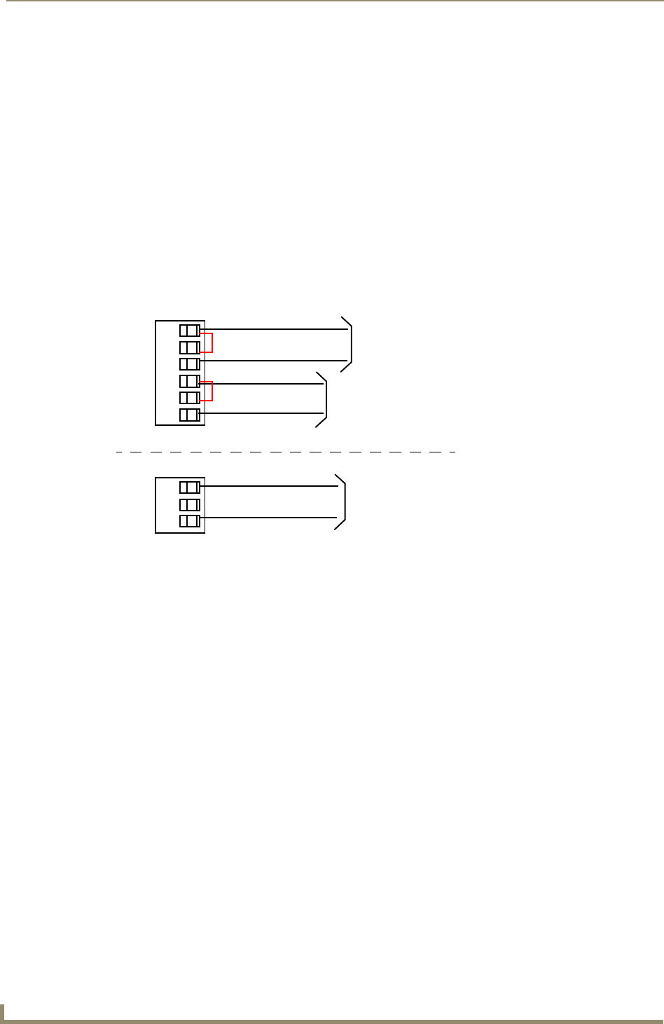
source and destination have separate main supplies. Use the following wiring drawing (FIG. 8) to
configure an unbalanced audio connection.
When using unbalanced audio for the AUDIO IN connector (FIG. 8), the "-" and the "GND" terminals
should be connected together and then connected to the GND of the unbalance audio signal. When
connecting to an unbalanced audio input from the MIC OUT connector (FIG. 8), wire the "+" terminal to
the signal input, and the "GND" terminal to the signal ground.
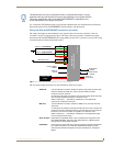
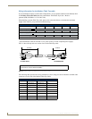
Wiring the NXA-AVB/ETHERNET for Balanced Audio
Professional audio equipment will often use balanced audio inputs and outputs, usually on 3-pin "XLR"
connectors. A balanced audio signal consists of a pair of wires carrying the audio signal in anti-phase
with each other (if one wire carries a positive voltage, the other carries an equal and opposite negative
voltage).
The advantage of balanced audio over unbalanced audio is its ability to reject external interference added
as the signal is carried over the wire. The receiving equipment takes the voltage difference between the
two wires as the input signal. Interference will usually get added to both wires equally, and so gets
cancelled by the receiving equipment.
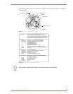
The 3 wires used in a typical XLR lead are often referred to as Ground, Live (Hot) and Return (Cold).
"Live" and "Return" carry the "in-phase" and "out-of-phase" versions of the audio respectively. The pins
of the XLR plug/socket are as follows:
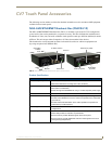
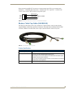
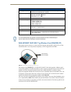
•PWR: 2-pin mini-Phoenix connector that connects to a 12 VDC-compliant power
supply. This port can be used to provide power to a Modero panel by sending it
through the NXA-AVB/ETHERNET (rear power connector through to the front
power connector).
FIG. 8
Wiring the rear AUDIO IN and MIC OUT for use with Unbalanced Audio
• X = Ground
• L = Live (Hot)
• R = Return (Cold)
Unbalanced IN
GND
IN-
IN+
GND
IN-
IN+
Left Channel
Right Channel
(Jumper IN- to GND)
Unbalanced OUT
GND
OUT-
OUT+
Microphone
Unbalanced IN
(Jumper IN- to GND)
AUDIO IN
MIC OUT